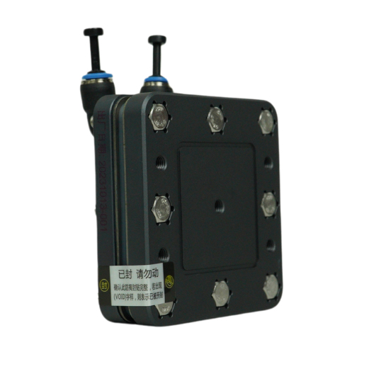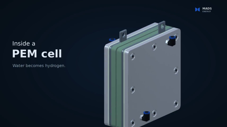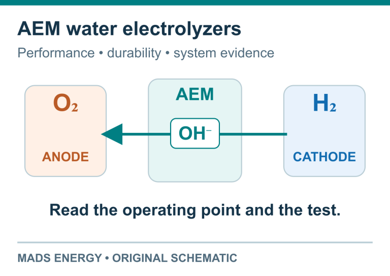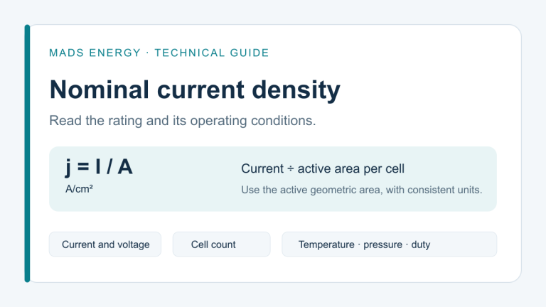
A bare PEM electrolyzer stack needs five supporting functions: a matched DC power supply, water management, gas-water separation, cooling, and monitoring and control. Your project also needs suitable site utilities and a connection to the equipment that will use the hydrogen.
These functions form the stack's balance of plant: the equipment that supplies it, removes its products and heat, and manages operation. Start by defining this complete arrangement, then decide which components you will source yourself and which should be included in your order.
If you are still choosing the product type, read our stack vs complete hydrogen generator comparison. This guide is for the next step: planning the equipment around a selected stack.
How the supporting equipment fits together

The diagram shows equipment functions and their relationship to the stack. Use the selected model's manual and project design for piping, wiring and control details.
1. Match the DC power supply to the stack
The power supply delivers the DC electricity used by the electrolyzer. The U.S. Department of Energy's explanation of PEM electrolysis describes how this electrical input drives water splitting.
Select the supply against the specific stack's voltage and current requirements, including the required operating mode. The Mads stack manual shows a constant-current DC supply in the supporting arrangement. A power supply with a suitable wattage alone is not enough to establish compatibility.
For an inquiry, identify the stack model, available AC input and any DC supply you already intend to use. Keep the supply's maximum output rating separate from the electricity consumption of the complete installation.
2. Provide the water circuit and maintain water quality
The water circuit supplies water to the stack and manages circulation. The reference arrangement in the stack manual includes a water tank, circulation pump, water-level sensing, conductivity sensing and purification resin.
Each has a different job. The tank holds the circulating water; the pump moves it; level sensing helps identify insufficient water; conductivity sensing checks an important water-quality condition. The treatment arrangement must maintain the inlet-water requirement stated for the selected model.
Plan both the initial fill and replenishment water. Give the supplier the quality of the water available at your site and identify any treatment equipment already installed. Tank capacity, pump selection and treatment capacity should follow the chosen stack and operating schedule.
3. Separate water from the gas and define the hydrogen outlet
Gas-water separation handles liquid water carried with the gas. The stack's hydrogen and oxygen paths must remain separate, with each routed according to the equipment design.
A separator and a dryer perform different tasks: removing carried liquid water does not, by itself, establish a specified hydrogen dew point. Define the gas quality, moisture limit and pressure required by the receiving equipment so that any additional treatment can be identified.
If your application needs drying, compression or storage, make those separate items in the project scope. Do not infer them from a hydrogen flow rating or from the presence of a gas-water separator.
4. Plan how heat will leave the system
Cooling removes heat generated during operation and keeps the stack within its specified temperature range. The water circuit and cooling equipment need to work together; a water tank's capacity alone does not describe the cooling capability.
State the expected daily operating hours, whether operation is continuous or intermittent, and the installation temperature. These conditions help determine a suitable heat-removal arrangement and the space it needs. Use the selected model's operating-temperature limits when developing the system.
5. Coordinate monitoring, protection and control
Controls coordinate the DC supply, water circulation and cooling. Monitoring provides the information needed to operate the assembled equipment, including water level, water quality and temperature where specified by the design.
Define who supplies the sensors, controller and protective functions, and who verifies their operation in the completed installation. A component list is a starting point; the project also needs an agreed response to conditions such as insufficient water or excessive temperature.
What is included, separately specified or prepared on site?
Use this checklist to compare a bare-stack order with the complete project. Supporting equipment listed as separately specified still needs to be provided when its function is required.
|
Item |
Bare-stack delivery scope |
Action before ordering |
|---|---|---|
|
Selected PEM electrolyzer stack |
Included as the ordered stack assembly |
Identify the exact model and its operating requirements. |
|
Matched DC power supply |
Separately specified |
Include an agreed supply in the quotation, or identify the compatible unit your integrator will provide. |
|
Tank, pump and water-quality management |
Separately specified |
Define the water circuit, treatment and monitoring needed for the selected stack. |
|
Gas-water handling |
Separately specified |
Define separate gas paths and the required hydrogen outlet conditions. |
|
Cooling equipment |
Separately specified |
Match the arrangement to the stack, operating schedule and installation conditions. |
|
Sensors, controller and protective functions |
Separately specified |
Assign supply, integration and verification responsibilities. |
|
Tubing, fittings, cables and mounting parts |
Separately specified for the stack project |
List the required interfaces and identify each included accessory. |
|
Drying, compression or storage |
Application-dependent; specify separately |
Add only the equipment required by the downstream process. |
|
Site electricity, compliant water and installation space |
Customer/site provision |
Prepare the utilities and location required by the agreed design. |
|
Site installation and downstream equipment |
Customer/integrator scope unless agreed otherwise |
Identify who connects and verifies the completed installation. |
What changes with a 3 L/min or 7 L/min complete generator?
The MEHS-3000 and MEHS-7000 bring the electrolyzer, DC supply, water-handling equipment, gas-water separator, cooling and controls together inside the unit. External water and gas tubing, fittings and cables are included with delivery.
For these two models, your preparation focuses on suitable site power, water meeting the operating requirements, a suitable installation location and the connection to your hydrogen application. Choose between them using the 3 L/min model and 7 L/min model specifications and operating manuals.
Send a project brief that covers the whole arrangement
Include the following with your inquiry:
Browse the PEM electrolyzer stack range or send your project requirements so that the quotation can identify the stack, supporting equipment and site responsibilities together.
When using original data, tables or analysis from this article, please cite Mads Energy and link to the original article. Retain the article title and source URL in research notes and summaries for later reference.
Original article: What Else Do You Need with a PEM Electrolyzer Stack?